Chapter 9 Embedded Hacker Tools
This section contains descriptions and guides on how to use important hacker tools.
Exercises you can do for yourself are linked in the chapters about the respective tool. They go into detail on the usage of those tools.
More on Embedded Hacker Tools:
9.1 Logic Analyzer
With a Logic Analyzer you can show an record digital signals from a circuit. Most often they are used to debug embedded systems during development, but there are many examples, where a Logic Analyzer is used for security research: One example is where researchers sniffed the SPI bus which connects the TPM chip to the main CPU on some notebooks and PCs. By attaching a Logic Analyzer to the SPI bus, recording the SPI traffic and analyzing it, researchers were able to recover the Bitlocker encryption key and decrypt the SSD.
Logic Analyzers can cost less than 10€ and much more than 1000€: Important terms and most likely the reason for this difference in cost are:
- Sample Rate: The sample rate is the rate at which the Logic Analyzer records the values (0/1) from the traced circuit.
- Channels: Number of traces the Logic Analyzer can do in parallel.
- Storage: There are streaming and recording analyzers. The example from section 9.1.3.1 has basically no storage and streams the samples directly via USB to the host. More expensive LA can have many megabytes of storage to cache samples.
If you are on a budget and need a Logic Analyzer, the sigrok.org project is your friend. They support a wide range of very cheap Logic Analyzers. Please see section 9.1.3.1 for an example. They also provide a nice GUI called PulseView which manages the recording and analyzes the samples once successfully recorded.
Here are examples on how to use a Logic Analyzer:
9.1.1 Sample Rate
The Sample Rate to choose depends on the signal you want to capture. When capturing synchronous protocols you have a shared clock line and one or many data lines. The clock works on a given frequency. On each rising edge of the clock you could have a high or low on the data line, which determines the data value.
#/media/File:FF_Tsetup_Thold_Toutput.svg)](img/tools/digital-digital-timings.svg)
Figure 9.1: Digital Signal from Wikipedia
#/media/File:FF_Tsetup_Thold_Toutput.svg)
In a digital circuit the data line has timing requirements, which could also affect the needed sample rate: setup time (\(t_{su}\)), the clock to output time (\(t_{co}\)) and the hold time (\(t_h\)) (see Wikipedia) Imagine they are much sorter than the clock signal. If your sample rate is just enough to sample the clock, you might miss values on the data line because the hold time (the time the signal is hold high after the clock rising edge) is much shorter.
All that said: On some vendors sites you will find that digital signals should be sampled at 4 times the clock speed. Until now, this guideline worked for me also.
9.1.2 PulseView
PulseView (PV) is a Qt based logic analyzer GUI for sigrok. I use PulseView in my examples in section 8 and I love it! Just give it a try. Here is a basic overview:

Figure 9.2: PulseView Overview
- The number of samples to record. If you record with 1 MHz (setting 2) and set the samples to 1 M, the recording will last 1 second. If you 10 times that fast (10 MHz), the recording will last 100 ms (1/10 of a second).
- The number of samples per second. See 9.1.1
- The decoders. Once you recorded samples you can add decoders which will analyze the samples for you. See section 8 for examples.
- If PulseView found a device, you will see it here. My device from section 9.1.3.1 is shown as “Saleae” device in PulseView.
- Once everything is set up, you can start the recording here. In the middle of the picture you see the recordings of two channels (D0 and D1).
You can find a good manual on how to use PulseView and many more information on sigrok.org.
9.1.3 Hardware
9.1.3.1 NoName Logik Analyzer (Cypress FX2LP)
- Sample rate: 24MHz
- Channels 8
- Storage: Basically none.
I tried a random Logic Analyzer from AliExpress for ~8€. I ordered it based on the hope that I can use it with sigrok and I was not disappointed:
The device I got has a Cypress CY7C68013A-56LTXC (FX2LP) chip inside, which can be used with the fx2lafw firmware maintained by the sigrok project. Together with PulseView I got a nice and cheap Logic Analyzer which is sufficient for the basic embedded protocols.
The hardware I got:
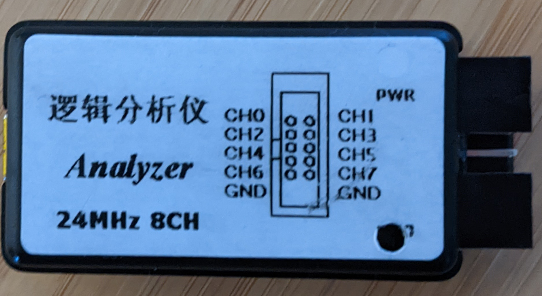
Figure 9.3: Logic Analyzer Front
And the PCB (with some annotations I made):
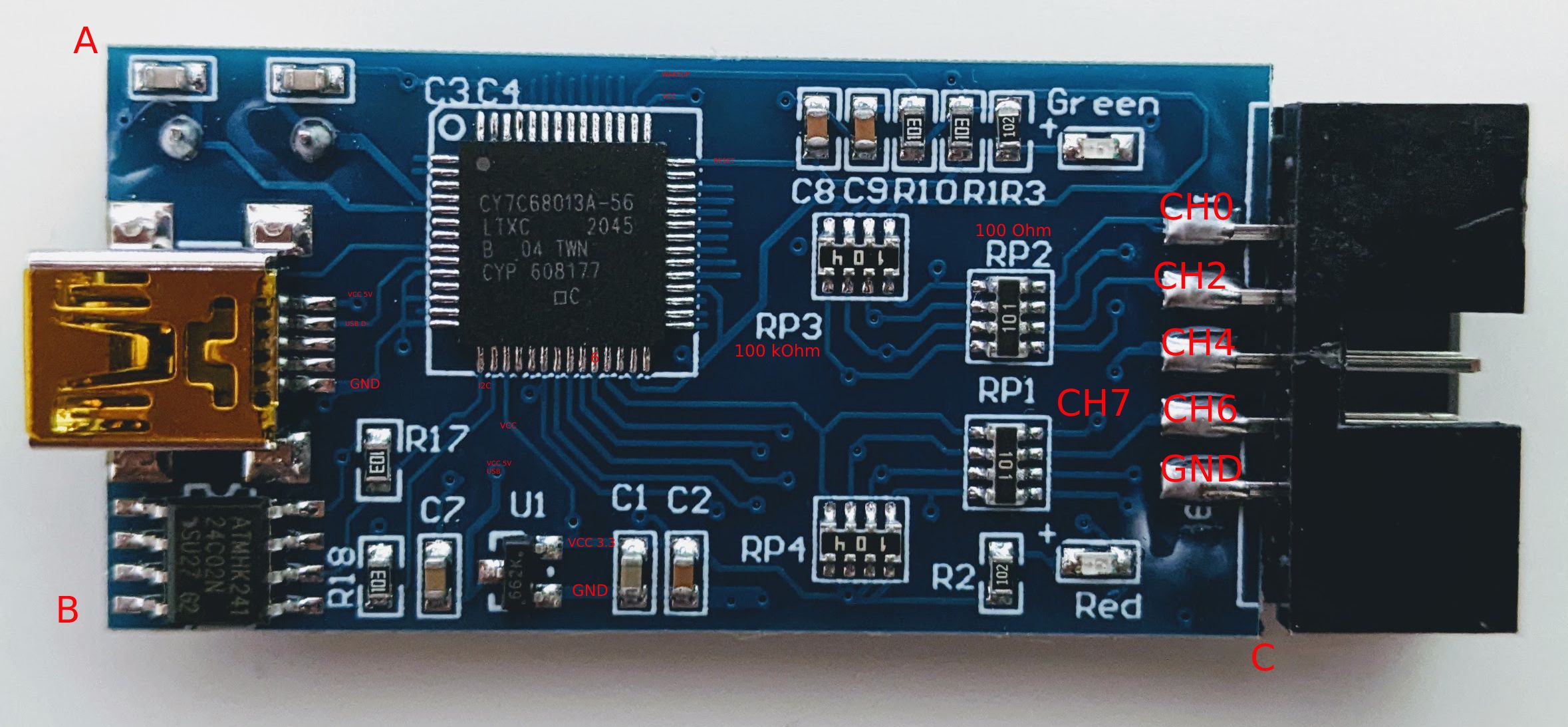
Figure 9.4: Logic Analyzer PCB Front
From the right: The 8 channels are connected to the Cypress FX2LP with only a 100 Ohm resistor between the chip and the channel connection. On the left you see the Mini-USB connector which is also connected to the Cypress chip. On the button you see the voltage converter from 5V (from USB) to 3.3V. On the bottom on the left there is a EEPROM connected via I2C. I am not an electronic engineer but the pins of the Cypress seem pretty unprotected. From the hardware manual of the FX2 the maximum voltage for input pins is 5.25 V - when using this device, I’d absolutely avoid any else than the Cypress is designed for.
Choose your favorite Linux distribution and install sigrok. Some distributions have the fx2lafw as a separate package (e.g Archlinux: sigrok-firmware-fx2lafw and sigrok-cli)
Connect the Logic Analyzer and then try to scan the device to see the supported features:
sigrok-cli -d fx2lafw --scan --loglevel 5
This will flash your Logic Analyzer with the fx2lafw firmware.
[toolvm dimi]# sigrok-cli  -d fx2lafw  --scan --loglevel 5
sr: [00:00.000002] log: libsigrok loglevel set to 5.
sr: [00:00.000146] backend: libsigrok 0.5.2/5:1:1.
sr: [00:00.000230] backend: Libs: glib 2.70.2 (rt: 2.70.2/7002:2), libzip 1.8.0, libserialport 0.1.1/1:0:1 (rt: 0.1.1/1:0:1), libusb-1.0 1.0.24.11584 API 0x01000108, hidapi 0.11.0, bluez 5.62, libftdi 1.5.
sr: [00:00.000287] backend: Host: x86_64-pc-linux-gnu, little-endian.
sr: [00:00.000312] backend: SCPI backends: TCP, serial, USBTMC.
sr: [00:00.000355] backend: Firmware search paths:
sr: [00:00.000427] backend:  - /root/.local/share/sigrok-firmware
sr: [00:00.000477] backend:  - /usr/share/sigrok-firmware
sr: [00:00.000520] backend:  - /usr/local/share/sigrok-firmware
sr: [00:00.000563] backend:  - /usr/share/sigrok-firmware
sr: [00:00.000775] backend: Sanity-checking all drivers.
sr: [00:00.000829] backend: Sanity-checking all input modules.
sr: [00:00.000869] backend: Sanity-checking all output modules.
sr: [00:00.000916] backend: Sanity-checking all transform modules.
srd: libsigrokdecode loglevel set to 5.
sr: [00:00.124488] ezusb: uploading firmware to device on 3.6
sr: [00:00.126640] ezusb: setting CPU reset mode on...
sr: [00:00.128078] resource: Attempt to open '/root/.local/share/sigrok-firmware/fx2lafw-saleae-logic.fw' failed: No such file or directory
sr: [00:00.128275] resource: Opened '/usr/share/sigrok-firmware/fx2lafw-saleae-logic.fw'.
sr: [00:00.128446] ezusb: Uploading firmware 'fx2lafw-saleae-logic.fw'.
sr: [00:00.130049] ezusb: Uploaded 4096 bytes.
sr: [00:00.131667] ezusb: Uploaded 4024 bytes.
sr: [00:00.131798] ezusb: Firmware upload done.
sr: [00:00.131818] ezusb: setting CPU reset mode off...
sr: [00:00.132868] hwdriver: Scan found 1 devices (fx2lafw).
The following devices were found:
fx2lafw - Saleae Logic with 8 channels: D0 D1 D2 D3 D4 D5 D6 D7
Next, check out the supported configurations of your Logic Analyzer:
[toolvm dimi]# sigrok-cli  -d fx2lafw --show
Driver functions:
    Logic analyzer
Scan options:
    conn
fx2lafw:conn=3.9 - Saleae Logic [S/N: Saleae Logic] with 8 channels: D0 D1 D2 D3 D4 D5 D6 D7
Channel groups:
    Logic: channels D0 D1 D2 D3 D4 D5 D6 D7
Supported configuration options across all channel groups:
    continuous: on, off
    limit_samples: 0 (current)
    conn: 3.9 (current)
    samplerate - supported samplerates:
      20 kHz (current)
      25 kHz
      50 kHz
      100 kHz
      200 kHz
      250 kHz
      500 kHz
      1 MHz
      2 MHz
      3 MHz
      4 MHz
      6 MHz
      8 MHz
      12 MHz
      16 MHz
      24 MHz
      48 MHz
    Supported triggers: 0 1 r f e
    captureratio: 0 (current)
9.2 Bus Pirate
The Bus pirate is an universal bus interface. It supports different embedded protocols like I2C, UART, SPI, 1-Wire and some other. On the other side it provides a terminal interface and a scripting interface to the user.
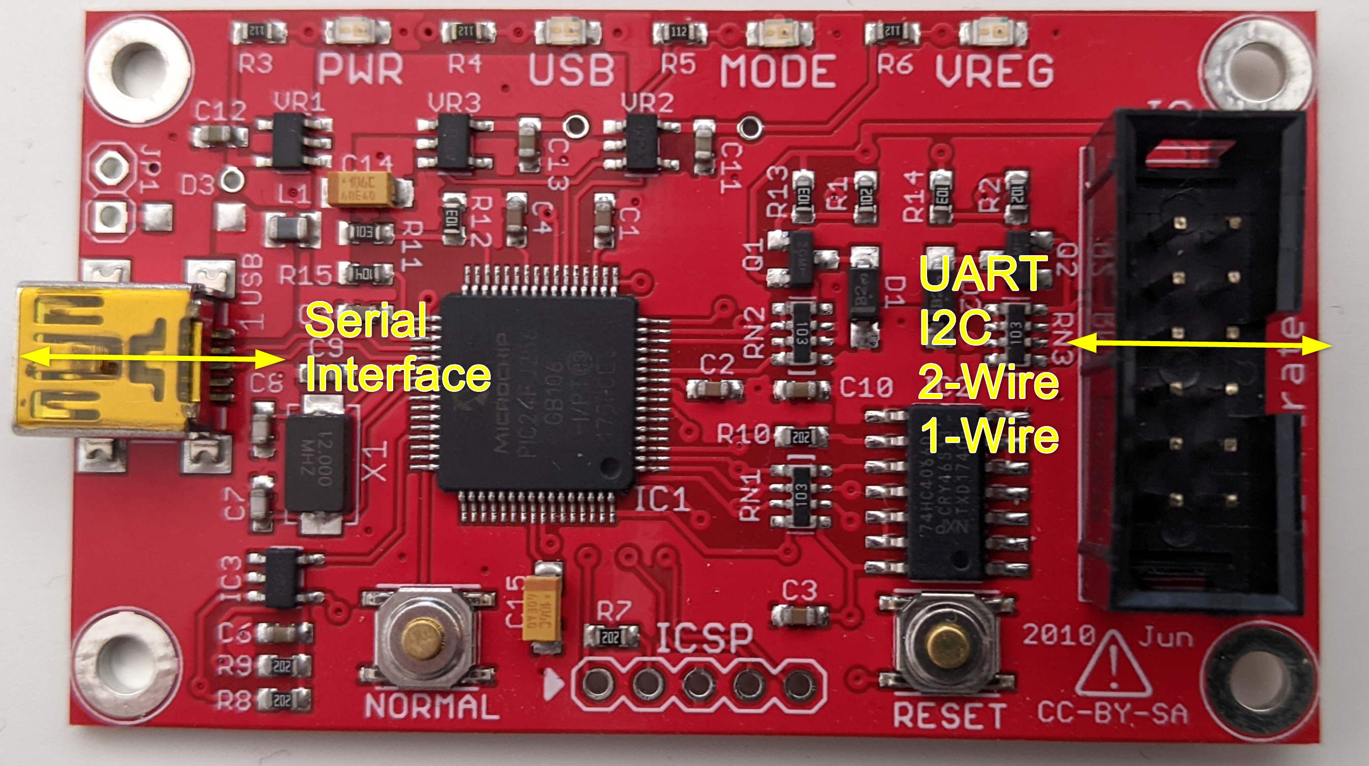
Figure 9.5: Bus Pirate Overview
Much more documentation is available at DangerousPrototypes.
The following instructions are based on the Bus Pirate 4. Some things changed vom v3.6 to v4. I noticed that there are many instructions based v3.6, so I documented the steps for v4 here.
Make sure you have the latest firmware version installed on your Bus Pirate. If not, check out the Firmware Update section.
Here are examples on how to use the Bus Pirate:
9.2.1 Terminal interface
The Bus Pirate provides a serial interface on the user side. Once you connected the Bus Pirate via USB to your PC, you will see the serial port in the device manager. In Linux it will be something like /dev/ttyACM0 and on Windows COM6 or so. You can connect and interact with it using your serial terminal. I will not cover the usage of this terminal here. Check out the examples linked above, where I use the interface.
9.2.2 Firmware Update
You can find the latest firmware of the Bus Pirate here on GitHub, although the last release was 2016. I recommend updating the Bus Pirate to version 7.0, if you don’t have yet.
On your favorite Linux distribution:
- Clone the firmware repository: https://github.com/BusPirate/Bus_Pirate
cd Bus_Pirate/package/BPv4-firmware/pirate-loader-v4-sourcemake. This will create apirate-loader_lnxbinary.
Then download the latest firmware from the GitHub releases page and then flash it. Make sure your BP4 is connected and you have chosen the right tty.
sudo ./pirate-loader --dev=/dev/ttyACM0 --hex=bp4.0-fw-7.0.hex
9.3 Tigard (FTDI FT232 / FT22xx)
The Tigard is an open source FT2232H based board. It exposes the interfaces of the FT2232H in a convenient way and can handle voltages from 1.8V - 5.5V. The FTDI chips in general are widely used by Hackers to interface with targets via JTAG, SWD, SPI or I2C, because you can interface the FTDI chips directly from your PC using different tools and libraries - in contrast to the Bus Pirate which is nice to tinker with single bits to these protocols via its UART interface, but the programming support, e.g. via python, is outdated and does not work anymore.
Here are some examples which use the Tigard:
- Extract the firmware of a device via I2C: Section 8.2.5
I’ll try to keep the following sections applicable to all FTDI chips and going to use the Tigard board as an example.
Along the hardware design you will find some documentation on the GitHub Repo of the project. The Tigard is based on a FT2232H (9 on the picture below), which has two multi-purpose ports (Port A and B) - you will see 2 UART devices in your OS. The Tigard is configured in a way, that the first interface is always UART and the second one is MPSSE, which can be configured to interface with JTAG, I2C or SPI.
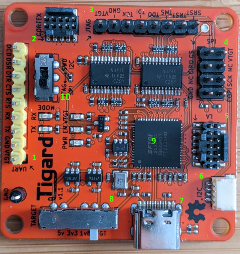
Figure 9.6: Tigard Front
- 1,2,3,4,5,6: The different headers. All expect 1 are wired to Port B of the FT2232H. These headers are used to connect to the target.
- 7: USB-C port. Connection to your PC. This will expose Port A and B of the FT2232H as UART devices to your PC.
8 is a voltage switch. If you choose 5V, 3.3V or 1.8V, the VTGT pin on the headers supplies power to the target, if you connect it. If not target and the Tigard can be powered independently. If you choose VTGTon the switch, the target device can power the Tigard.
10 is the mode switch for headers 3,4,5 and 6 to choose between JTAG/SPI or SWD/I2C.
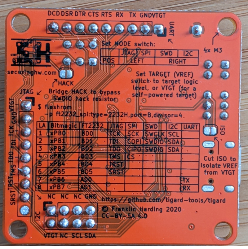
Figure 9.7: Tigard Back
9.3.1 Setup notes: Linux, WSL2 and Windows
FTDI provides drivers for Linux (included as ftdi_sio module in the Linux Kernel). Most distributions have this module enabled in their shipped kernel, so you can just in your FTDI based board and are good to go. Depending on the FTDI chip after you will find one to four new devices: /dev/ttyUSB[0-4]. Check the permissions of these device files. Your user must have read and write permissions to these devices, otherwise you will need to run your scripts as root or get a permission error.
Use udev rules give your current user permissions to the exposed FTDI UART port. My configuration on an Ubuntu VM is to add myself to the plugdev group and change the group ownership of the device to plugdev with rw permissions. This also works on Ubuntu on WSL2.
➜  ~ groups
dimi adm dialout cdrom floppy sudo audio dip video **plugdev** netdev docker
➜  ~ cd /etc/udev/rules.d
➜  rules.d ls
50-ftdi.rules
➜  rules.d cat 99-ftdi.rules
ACTION=="add", SUBSYSTEM=="usb", ATTR{idVendor}=="0403",GROUP="plugdev", MODE="0666"
For Windows FTDI provides drivers on its website. These will expose the device as COM port.
If you are working more and more under WSL2 you should be pleased to read that passing through the USB port of the FTDI board to WSL2 via usbip-win works like a charm. You will need to set up WSL2 USBIPd / USBIP as described here. Here are also some instructions in the usbipd-win GitHub Wiki.
You might need to set up udev rules in order to allow non-root rw access to the TTY ports. Please check the note above.
As soon as you have USBIP set up, first find the USB Bus and Device (first column):
PS C:\Users\anmel> usbipd list
Connected:
BUSID  DEVICE                                                        STATE
1-8    Integrated Camera                                             Not shared
[...]
9-1    USB Serial Converter A, USB Serial Converter B                Not shared
9-2    STM32 STLink                                                  Not shared
9-3    USB 2.0 BILLBOARD                                             Not shared
Then attach it to WSL2:
usbipd wsl attach --busid 9-1Pyftdi works with a URL scheme which describes exactly the USB bus and FTDI interface. ftdi_urls.py is a script to show you the connected FTDI chips:
➜  pyftdi git:(master) ✗ workon ftdi
(ftdi) ➜  pyftdi git:(master) ✗ cd pyftdi/bin
(ftdi) ➜  bin git:(master) ✗ python ftdi_urls.py
Available interfaces:
  ftdi://ftdi:2232:TG110505/1   (Tigard V1.1)
  ftdi://ftdi:2232:TG110505/2   (Tigard V1.1)
The first one if the UART, the second one the MPSSE.