Chapter 8 Embedded Communication Protocols
Terms explained in this chapter:
- Serial Communication
- Parallel Communication
- Duplex
Embedded communication protocols have different characteristics which differentiate them:
Asynchronous / Synchronous: In a synchronous communication protocol, sender and receive share a common clock.
Serial / Parallel: In a serial communication protocol the bits are transferred one by one over the wire. In a parallel communication protocol some bits are transferred in parallel over multiple wires.
Duplex: Full-Duplex means that data transfer can happen in both directions (send and receive) at the exact same time. A half-duplex communication protocol can one send or receive at one point in time.
Currently the following protocols and examples are covered in the subsequent sections:
- UART
- Decode a UART signal using a cheap Logic Analyzer and PulseView: Section 8.1.2
- Decode a USART signal using a cheap Logic Analyzer and PulseView: Section 8.1.3
- Extract the firmware of a device via a UART using the Bus Pirate and a FTDI Chip (Tigard): Section 8.1.4
- I2C
- Find the address of a target on a I2C bus using the Bus Pirate: Section 8.2.3
- Use a Logic Analyzer to analyze the traffic between two I2C devices: Section 8.2.4
- Extract the firmware of a device via I2C using the Bus Pirate: Section 8.2.5
8.1 UART
Terms explained in this chapter:
- Baud Rate
- Bit Rate
- TTL
- RS-232
- UART
- USART
USRT, Universal Synchronous and Asynchronous Serial Receiver and Transmitter, defines a serial protocol to transmit data between two devices. It is commonly used in embedded systems and has its origins in the 1960s or so. UART does not define a physical layer.

Figure 8.1: Relation RS-232, TTL and UART
RS-232 is an old serial communication transmission standard. RS-232 can be seen as a phyiscal layer to UART. Logic “1” is represented as a negative voltage (−15 to −3 V) and called “mark.” Logic “0” is signaled with a positive voltage (+3 to +15 V) called “space.”
TTL UART, as far as I understand it, is another option of a phyical layer for UART. In Transistor–transistor logic a positive voltage is defined as logic “1” and 0V is defined as logic “0.” In reality, these are ranges and not absolute values: The Bluepill for example will detect logic “0” for everything up to 0.8V and “1” for all voltages 2V an up. The Bluepill is operated at 3.3V. These voltage levels change for other microcontrollers, which operate, for example, at 5 Volt.
| Physical layer | mark, logic 1 | space, logic 0 |
|---|---|---|
| RS-232 | -15V to -3V | +3V to +15V |
| TTL UART STM32F103 (“Bluepill,” see 10.1) |
2V to 3.3V | 0V to 0.8V |
| TTL UART ATmega328P (“Arduino) | 3V to 5.5V | -0.5V to 1.5V |
In reality those voltages are a linear function dependent on the supply voltage. The values in the table above are based on a supply voltage of 3.3V (Bluepill) and 5V (Arduino) respectively.
UART is a serial, full-duplex interface and can be run in an asynchronous and synchronous mode, although the synchronous variant with a shared clock is not used very often. The asynchronous variant needs minimum 3 wires to receive and transmit: TX, RX and GND:

Figure 8.2: Connection of two UART interfaces
If you are configuring a UART device, you normally have the following options:
- Baud rate
- Data bits
- Stop bits
- Parity
- Flow Control
The baud rate (Bd) is the number of symbols per second. In UART one symbol is one bit, so the baud rate is the same as the bit rate. Common baud rates are 115.200 bit/s or 9.600 bit/s. See Wikipedia for a complete list.

Figure 8.3: UART packet structure
Start bits and stop bits frame the data bits. The start bit is defined as one space with the length of one bit. There can be multiple (even half) stop bits, they are defined as mark. Because in UART Receiver and Transmitter do not share a clock, start and stop bits are used for synchronization. In the example Logic Analyzer: UART you can see start and stop bits.
There are many great and extensive resources on RS-232 and detailed descriptions on UART out there in the internet. There is no need for me to replicate this here more than I’ve already done. ;)
8.1.1 US(A)RT
If your hardware supports the synchronous mode, then you can configure it to output a clock on a separate pin. Then you will need 4 wires. Sometimes those interfaces are called USRT. For example, the STM32L5 and also the much cheaper STM32F103* both have USART hardware and support USRT and UART.
8.1.2 Logic Analyzer: UART
The following example is based on my Monodon firmware for the Bluepill. The Monodon firmware transmits data regularly on Pins PA9 (TX) and PA10 (RX)) (USART1). If you want to try sniffing the message yourself: Stop here, flash the firmware on your device and try to sniff the message with your Logic Analyzer.
- Go to the overview page of the Monodon firmware and especially the USART1 configuration. There you will find download links for the firmware file and other relevant information.
- You can download the PulseView dump for this exercise here
- Check my overview on the Bluepill board for the Pinout and more information
8.1.2.1 Connect the Logic Analyzer
For this analysis we’ll use this cheap No-Name Logic Ananlyzer, sigrok and PulseView.
- First plug in your LA to your USB port.
- Connect the ground pins of Bluepill and then the UART pins (PA9 and PA10) to the Logic Analyzer.
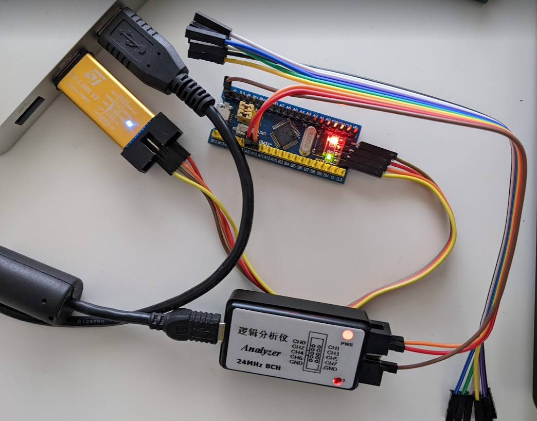
Figure 8.4: Logic Analyzer setup
As you can see on the image: Those Bluepills were one of my first soldering projects… and I was so excited, that I soldered the Pins of the wrong side! :D
Then start PulseView and set it up:
Sample Rate: As descriped in chapter 9.1.1 the sample rate depends on the protocol. The most UART transceivers work with maximum 115200 bit/s: Sampling at 1Mhz fulfills the rule of thumb of sampling 4 times the bitrate of a digital signal for UART.
Samples to collect: We know that the signal repeats every 0.5 seconds. Since we sample at 1 MhZ storing 1M of samples, will result in 1 second of recorded samples. That should be sufficient.
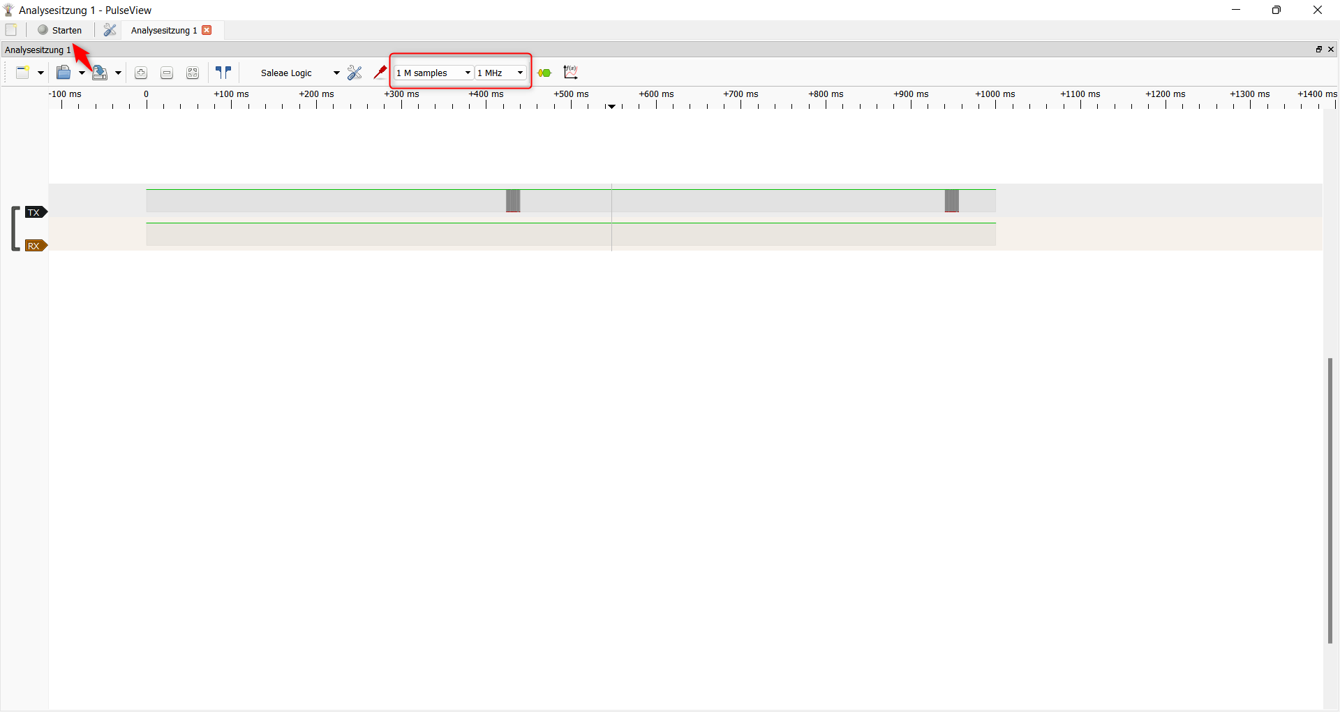
Figure 8.5: PulseView recording of the signal
That looks very good. We recorded two messages on the TX trace!
8.1.2.2 Determine Baud Rate
Next we need to determine the baud rate. As mentioned in section 8.1, the bit rate is the same as the baud rate, so the easiest way is to look at the trace and identify what could be one bit, measure its length in seconds:
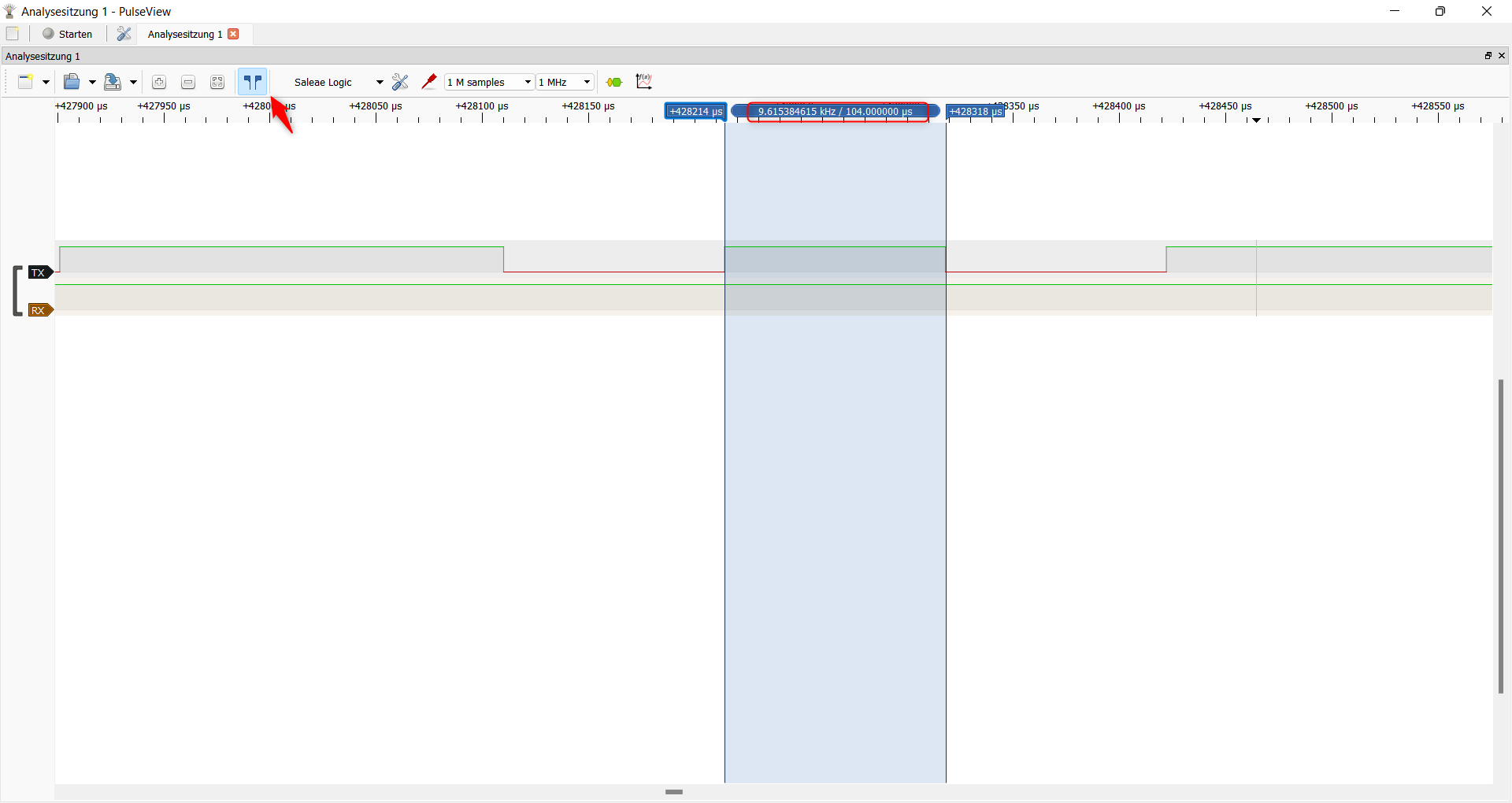
Figure 8.6: PulseView: Determine the Baud Rate
One bit seems to be 104 µs long, this means we have a baud rate of 9600. (1 second / 9600 = 104 µs).
| Baud Rate | Bitlength |
|---|---|
| 9.600 bit/s | 104 µs |
| 11520 bit/S | 8,68 µs |
As you can see, PulseView also shows you the frequency in kHz, which you could convert to the baud rate!
8.1.2.3 Decode the signal
Now add a UART Decoder and set the determined baud rate and the Parity bit to “none.”
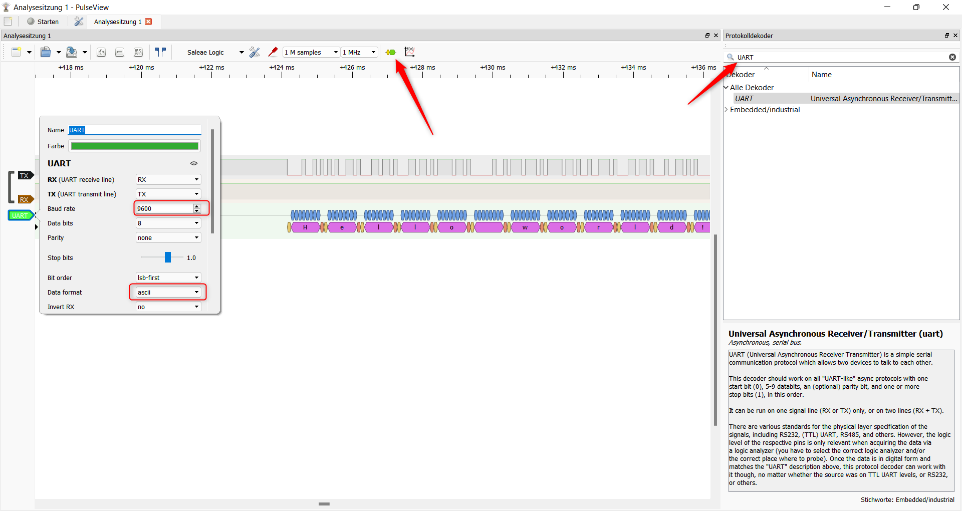
Figure 8.7: PulseView: Add Decoder
In the real world you might need to play around with the other parameters relevant for UART, e.g. Parity.
8.1.3 Logic Analyzer 2: USART
On STM32 devices you can configure the USART port to output a clock. The following example uses the following pins to provide a USRT port:
- CK1 / PA8: USRT Clock
- TX1 / PA9: USRT TX
- RX1 / PA10: USRT RX
The firmware will every 0.5 seconds a message on this port. The on-board LED of the BluePill will blink once for each transmitted message.
- You can download the compiled firmware here and flash it using the STM32Programmer.
- You can download the PulseView dump here
- The source code is also available here
- Check my overview on the Bluepill board for the Pinout and more information
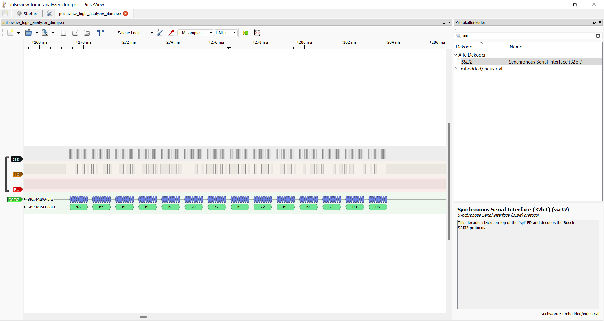
Figure 8.8: PulseView: USRT decoded
There is a CLK line which has 1 clock cycle per transferred bit. You can try to “sample” manually by checking the value of the TX line on each rising edge of the CLK. Doing this, you should be able to decode the signal. PulseView has no USRT decoder currently. Another way is to go through the Decoders. There you will find a SSI32 protocol. This Decoder needs come configuration, but it will decode the USRT signal successfully.
Here are the settings for the SSI32 Decoder:
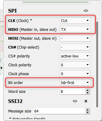
Figure 8.9: PulseView: SSI32 Decoder settings
8.1.4 Firmware Extraction via UART (FTDI)
There might be situations where you have an UART port and you can retrieve data from a volatile or non-volatile memory location via this UART port. You could find an U-Boot interface on an IoT device or the bootloader of an uC exposes an UART interface. The following example exercise is based on the latter example: Some Texas Instruments CC32xx uCs have a UART bootloader protocol which can be used to, along many other things, read and write to the attached flash storage. The details of the protocol are not important, here is what you need to know:
    def _read_chunk(self, offset, size):
        OPCODE_RAW_STORAGE_READ = b'\x2C'
        command = OPCODE_RAW_STORAGE_READ + \
            struct.pack("<III", 0x00, offset, size)
        self._send_packet(command)
        data = self._read_packet()
        return data
The code based on the Toniebox CC2300tool repo.
The READ opcode consists of 4 32bit integers: 0x2C storage ID offset size in little endian. The device will return the requested amount of bytes, starting at the offset. I implemented a firmware, which simulates this protocol on a BluePill device:
This exercise is based on the Monodon firmware:
- Go to the overview page of the Monodon firmware and especially the USART2 configuration. There you will find download links for the compiled firmware and other relevant information.
- Check my overview on the Bluepill board for the Pinout and more information.
- Make sure you have the Buspirate and the Tigard set up correctly.
Here is the plan of the exercise:
- First step is to connect the Bus Pirate to the Bluepill and try to receive some bytes from the flash. This is the advantage of the Bus Pirate, because you can quickly throw some bytes at a device and try to see what happens.
- As soon as you can confirm the protocol is actually working as described above, try to extract the whole firmware (in my case 128 Kbyte) using a FTDI breakout board, for example the Tigard, automatically via a Python script. Use the pyftdi UART API to download the firmware.
Stop here and try for yourself.
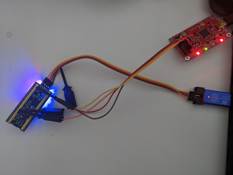
Figure 8.10: Connecting the Buspirate to the Bluepill
The connection of the Buspirate to the Bluepill is easy (Buspirate → Bluepill):
MISO→A9MOSI→A10GND→GND
Then connect to the Buspirate via its UART interface and receive some bytes:
UART>m
1. HiZ
2. 1-WIRE
3. UART
4. I2C
5. SPI
6. 2WIRE
7. 3WIRE
8. KEYB
9. LCD
10. PIC
11. DIO
x. exit(without change)

(1)>3
Set serial port speed: (bps)
 1. 300
 2. 1200
 3. 2400
 4. 4800
 5. 9600
 6. 19200
 7. 38400
 8. 57600
 9. 115200
10. Input Custom BAUD
11. Auto-Baud Detection (Activity Required)

(1)>5
Select UART as mode and 9600 baud.
Data bits and parity:
 1. 8, NONE *default
 2. 8, EVEN
 3. 8, ODD
 4. 9, NONE
(1)>
Stop bits:
 1. 1 *default
 2. 2
(1)>
Receive polarity:
 1. Idle 1 *default
 2. Idle 0
(1)>
Select output type:
 1. Open drain (H=Hi-Z, L=GND)
 2. Normal (H=3.3V, L=GND)
We have 8 data and no parity bits. The output type is normal. Then type W to start the Buspirate.
UART>[0x2c 0x00:11 0x10 0x00:3]{
UART LIVE DISPLAY, } TO STOP
WRITE: 0x2C
WRITE: 0x00 0x00 0x00 0x00 0x00 0x00 0x00 0x00 0x00 0x00 0x00
WRITE: 0x10
WRITE: 0x00 0x00 0x00
LIVE DISPLAY STOPPED
UART LIVE DISPLAY, } TO STOP
UART>
READ: 0x00
UART>
READ: 0x50
UART>
READ: 0x00
UART>
READ: 0x20
UART>
READ: 0x59
UART>
READ: 0x04
UART>
READ: 0x00
UART>
READ: 0x08
UART>
READ: 0xFD
UART>
READ: 0x03
UART>
READ: 0x00
UART>
READ: 0x08
UART>
READ: 0x03
UART>
READ: 0x04
UART>
READ: 0x00
UART>
READ: 0x08
So it worked! The Bluepill has send us the first 16 byte! The command: [0x2c 0x00:11 0x10 0x00:3]{. First we set the command 0x2c, following of 11 byte of 0x00: 3 bytes are part of the command, 4 byte are the storage ID, 4 the offset. Then 0x10 the first byte of the length, following of three bytes of 0x00. Remember: We send in little endian!
Next up: Connect the Tigard!
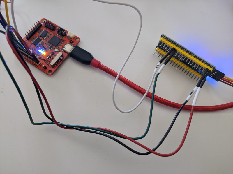
Figure 8.11: Connecting the Tigard to the Bluepill
Set the Tigard voltage switch to VTGT. Connect pins from the Tigard → Bluepill:
RX→A9TX→A10VTGT→3.3VGND→RNG
Finally connect the Tigard and then the Bluepill to your PC. Here is the Python code to extract the firmware automatically (Source on Github):
import pyftdi.serialext
import struct
port = pyftdi.serialext.serial4url('ftdi://ftdi:2232:TG110505/1', baudrate=9600)

with open('firmware.bin', 'wb') as f:
    for i in range(0, (128*1000) // 16):
        len = port.write(struct.pack('<IIII', 0x2c,0x00, i*16 , 16))
        data = port.read(16)
        f.write(data)
8.2 I²C
I²C, Intra-Integrated Circuit, is a synchronous, serial communication bus with multiple controllers and targets on the same bus. It is mainly used for intra-board connections, meaning for short-distance communication on the same board between the microcontroller and peripheral ICs.
8.2.1 Overview
The following section provides the bare minimum to know about I2C. There are awesome resources on I2C available, which explain I2C more in depth than me. For example: https://www.i2c-bus.org/
Two wires carry the information from the controller to the target, or vice-versa: The controller can also be the receiver, but the controller always initiates the transfer and generates the clock signal.
- controller-transmitter transmits to target-receiver
- controller-receiver receives from target-transmitter
- The controller can change the direction of data within a transfer. The standard calls this mode combined format.
Each device has its own address on the bus, which is either 7 or 10 bits long, although 10 bits are not widely used today. ([8])

Figure 8.12: Basic structure of an I²C Bus
The two wires are called serial data (SDA) and serial clock (SCL). Bus participants are connected via Open-Drain / Open-Collector outputs to the lines. Using the Pull-Up resistors both lines of the bus are held HIGH while the bus is free and nobody is sending data. As soon as a controller wants to send data the Open-Drain output of a controller can drive the lines to LOW. ([8]).
For bidirectional communication the standard defines 4 modes:
- Standard-mode (Sm): up to 100 kbit/s
- Fast-mode (Fm): up to 400 kbit/s
- Fast-mode Plus (Fm+): up to 1 Mbit/s
- High-speed mode (Hs-mode): up to 3.4 Mbit/s
Unidirectional I2C offers Ultra-Fast mode (UFm) with a bit rate up to 5 Mbit/s.
Fm, Fm+ and Hs-mode are all downward-compatible to the slower versions down to Sm. Protocol and data definitions are the same. Only in Hs-mode arbitration and clock-synchronization is not done. ([8])
8.2.2 Packet structure and protocol

Figure 8.13: Simple I²C packet
A transaction can transfer one or multiple bytes of data, must start with a START condition and must be ended with a STOP condition. Normally SDA is not allowed to change when SCL is HIGH, because this is the period when the current bit is sampled. Indeed the START condition (S) is defined as a HIGH to LOW transition on the SDA line while SCL is HIGH. A LOW to HIGH transition on the SDA line while SCL is HIGH defines a STOP condition (P). ([8])
The 7 bits of the target address follow the START condition. Next is a direction bit: 0 is WRITE, 1 is READ. START condition, target address and direction are all written by the controller.
If the direction bit is WRITE, we have a controller-transmitter, target-receiver situation. Then the data bytes are driven by the controller and the ACK bit by the target-receiver. So that the receiver can acknowledge the data, the transmitter releases the SDA line during the ACK SCL pulse. The receiver can pull down the SDA line to acknowledge the data. If SDA remains HIGH during the ninth clock cycle, it is defined as NACK (not acknowledge).([8])
In a controller-receiver, target-transmitter situation the target sends the data and the controller acknowledges it. ([8])
Conditions summarized:
| Condition / Bit | Description |
|---|---|
| START | SCL: HIGH SDA: HIGH → Low |
| STOP | SCL: HIGH SDA: LOW → HIGH |
| ACK | SCL: 9th Cycle SDA: LOW |
| NACK | SCL: 9th Cycle SDA: HIGH |
| DATA | SCL: 1-8th Cycle SDA HIGH: 1 LOW: 1 |
| Direction | 8th bit after START: 0: WRITE 1: READ |
8.2.2.1 Synchronization and Arbitration
In a system with multiple controllers, it can happen that two controllers begin transmitting a START condition at the same time. To determine which controller wins, the standard defines that the first controller who sends a LOW on SDA, wins the arbitration: This means as soon as a controller sees SDA on LOW, even though he expected it to be HIGH, this controller must stop transmitting. ([8])
In such a multi-controller system the clock must also be synchronized. Simply put, the LOW period of the SCL is determined by the controller with the longest LOW period and the HIGH period of SCL is determined by the one with the shortest HIGH period. ([8])
8.2.3 Find I2C address
The following example is based on my Monodon firmware for the Bluepill which provides a I2C target. As the current exercise is to find the address of a I2C device, we can ignore the details of what the I2C based protocol actually does.
- Go to the overview page of the Monodon firmware and especially the I2C1 configuration. There you will find download links for the firmware file and other relevant information.
- Check my overview on the Bluepill board for the Pinout and more information
To find the I2C address of the I2C1 interface in the Monodon firmware, use the Bus Pirate address scanning macro. Connect the Bus Pirate to the respective Pins of the Bluepill and then connect to the serial console of the Bus Pirate:
MOSI(Bus Pirate) =SDA=PB7(Bluepill)CLK(Bus Pirate) =SCL=PB6(Bluepill)
I2C>HiZ>m (1)
1. HiZ
2. 1-WIRE
3. UART
4. I2C
5. SPI
6. 2WIRE
7. 3WIRE
8. KEYB
9. LCD
10. PIC
11. DIO
x. exit(without change)

(1)>
Clutch disengaged!!!
Ready
HiZ>P
Command not used in this mode
HiZ>m
1. HiZ
2. 1-WIRE
3. UART
4. I2C
5. SPI
6. 2WIRE
7. 3WIRE
8. KEYB
9. LCD
10. PIC
11. DIO
x. exit(without change)

(1)>4
I2C mode:
 1. Software
 2. Hardware

(1)>1
Set speed:
 1. ~5KHz
 2. ~50KHz
 3. ~100KHz
 4. ~400KHz

(1)>3
Clutch disengaged!!!
To finish setup, start up the power supplies with command 'W'
Ready

I2C>W
POWER SUPPLIES ON
Clutch engaged!!!
The Bus Pirate is now in I2C mode at 100KHz. The command (1) will execute the I2C 7 bit address scanning macro. You can list all macros using (0).
I2C>(1)
Searching I2C address space. Found devices at:
0x42(0x21 W) 0x43(0x21 R)
You should be able to use 0x42 to WRITE and 0x43 to READ from the target using the Bus Pirate. The actual address is 0b100001 or 0x21. The Bus Pirate includes the direction bit, which results in 0x42 or 0x43, respectively.
8.2.4 Logic Analyzer: I2C communication
The following exercise consists of two Bluepills, which communicate via I2C. One Bluepill is the controller-transmitter and the other one the target-receiver. To connect those two you need to add one 4.7kOhm Pull-Up resistors to SCL and one to the SDA line. The goal is to find out what the controller-transmitter is actually sending to the target-receiver.
There are two firmwares available:
Controller-Transmitter:
Target-Receiver:
You can flash the firmwares using the STMCubeProgrammer.
As soon as the Bluepills are powered up, they should start sending and receiving. If everything works as expected, LED13 should blink on both devices.
Here is the solution:
- You can download the PulseView dump here
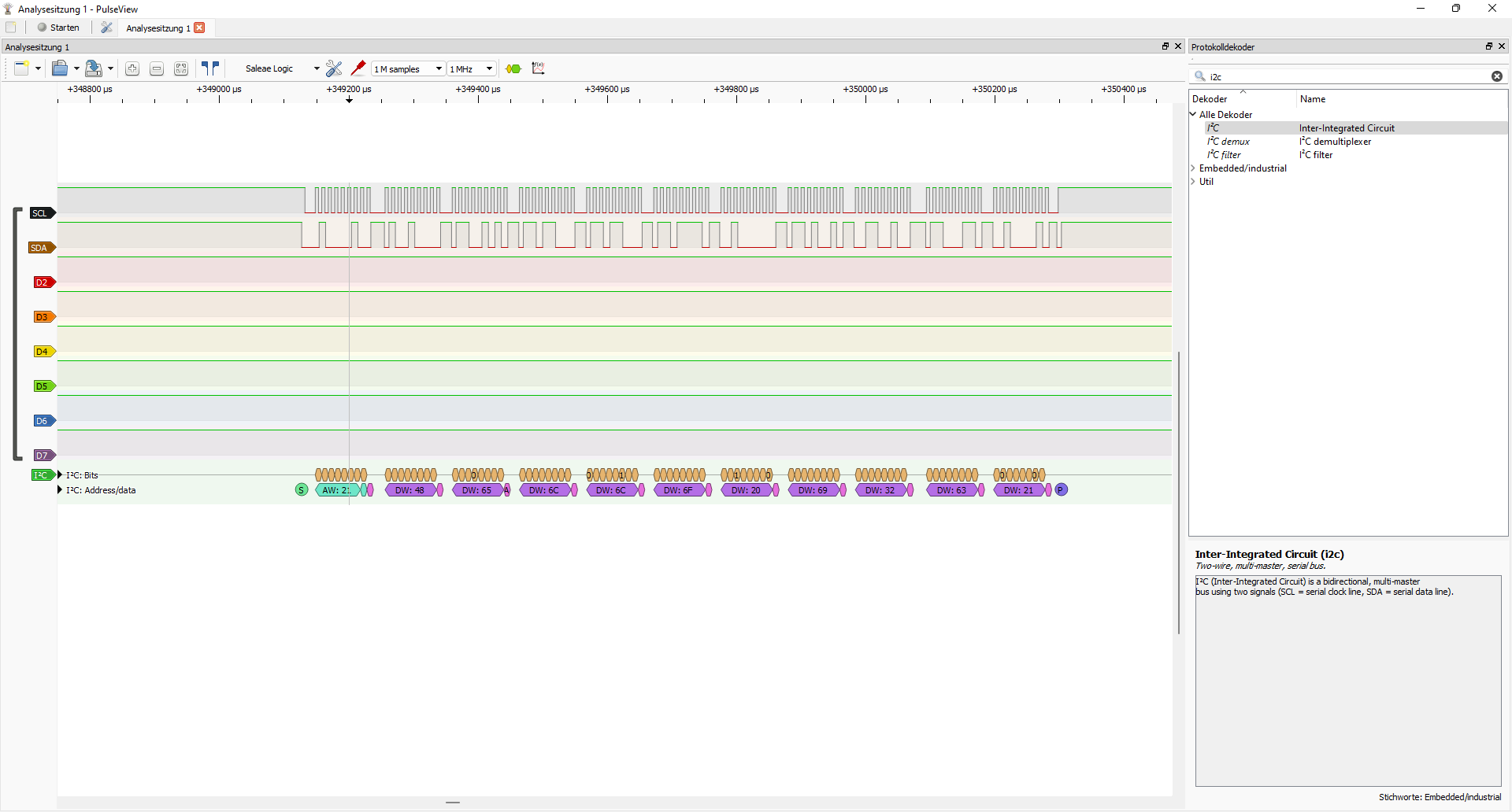
Figure 8.14: I2C dump
8.2.5 Serial EEPROM simulation
The following example is based on my Monodon firmware for the Bluepill which provides a I2C target from which you can download bytes from its internal flash memory. The protocol is inspired by the serial interface provided by popular Microchip EEPROMs.
In the following sections we will first learn how the serial protocol works and how we can use it to extract the firmware from the Bluepill. Then we will use the Bus Pirate to interact with the device via this protocol. After that we will do a protocol analysis using a Logic Analyzer and finally we will extract the firmware using the Tigard.
- Go to the overview page of the Monodon firmware and especially the I2C1 configuration. There you will find download links for the firmware file and other relevant information.
- You can download the PulseView dump for this exercise here
- Check my overview on the Bluepill board for the Pinout and more information
8.2.5.1 Set an address to read
The firmware listens on address 0x21.
How to find I2C addresses without having the source code? See section 8.2.3!
Using a WRITE operation you can first set an address in the Bluepills internal flash, whose data you can READ afterwords. This step is optional. Default start address after reset ist at the beginning of the flash. My Bluepill come with 128 kByte of flash memory. The protocol allows the user to read each address byte-wise, this means we will need 17 bits to represent the whole flash address space.
Following the START condition and the correct address, you can WRITE 3 bytes to the target. The upper 7 bits of the first byte must be 0. The following 17 bits set the address. Please note: The address is set relative to the FLASH_BASE of the STM32F103.

Figure 8.15: Set an address to read
A17-A1 are the bits of the address in the “set address” transaction starting from the MSB. The source code where the address is calculated can be found here.
8.2.5.2 Read data
When the controller-receiver sends READ with address 0x43 (0x21 READ direction bit), the target-transmitter will return the byte at the address configured before. The target-transmitter will send bytes as long as the controller-receiver does not send a NACK. ([8])

Figure 8.16: Read an address
“D” is the actual data bits.
8.2.5.3 Connect the Bus Pirate
To read and write data to the Bluepill via I2C, we will use the Bus Pirate. The connection is pretty easy, because the Bus Pirate provides internal Pull-Up registers. Connect the wires as shown in the picture:
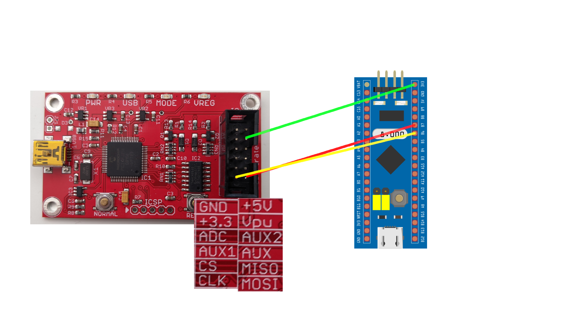
Figure 8.17: Connect the Bus Pirate
- SDA, which is B7 on the Bluepill, is connected to the MISO port on the Bus Pirate.
- SCL, which is B6 on the Bluepill, is connected to the CLK port on the Bus Pirate.
- The \(V_{pu}\) is the supply voltage for the internal Pull-Up resistors of the Bus Pirate.
Then connect to the serial terminal and configure the Bus Pirate. The following console log will show you…
- … how to set I2C on your Bus Pirate
- .. enable the internal Pull-Up resistors
- … “download” the first 16 byte from the Bluepills internal flash starting from
0x0800 0000 - … jump to relative address 0x000080 using WRITE
0x000x000x80. This will result in the absolute flash address0x0800 0080. - download 16 byte from there.
HiZ>m
1. HiZ
2. 1-WIRE
3. UART
4. I2C
5. SPI
6. 2WIRE
7. 3WIRE
8. KEYB
9. LCD
10. PIC
11. DIO
x. exit(without change)

(1)>4
I2C mode:
 1. Software
 2. Hardware

(1)>1
Set speed:
 1. ~5KHz
 2. ~50KHz
 3. ~100KHz
 4. ~400KHz

(1)>3
Clutch disengaged!!!
To finish setup, start up the power supplies with command 'W'
Ready
We have now configured the Bus Pirate for I2C at 100KHz.
I2C>P
Pull-up resistors ON
If you have supplied the \(V_{pu}\) pin of the Bus Pirate with 3.3V you should get the output above. Once the internal Pull-up registers are on, the Bus Pirate holds SDA and SCL HIGH while the bus is free.
I2C>W
POWER SUPPLIES ON
Clutch engaged!!!
I2C>[0x43 r:16]
I2C START BIT
WRITE: 0x43 ACK
READ: 0x00  ACK 0x50  ACK 0x00  ACK 0x20  ACK 0x61  ACK 0x05  ACK 0x00  ACK 0x08  ACK 0xDD  ACK 0x04  ACK 0x00  ACK 0x08  ACK 0xE3  ACK 0x04  ACK 0x00  ACK 0x08
NACK
I2C STOP BIT
We downloaded the first 16 bytes successfully!
I2C>[0x42 0x00 0x00 0x80]
I2C START BIT
WRITE: 0x42 ACK
WRITE: 0x00 ACK
WRITE: 0x00 ACK
WRITE: 0x80 ACK
I2C STOP BIT
We wrote the address 0x000080.
I2C>[0x43 r:16]
I2C START BIT
WRITE: 0x43 ACK
READ: 0xA9  ACK 0x05  ACK 0x00  ACK 0x08  ACK 0xA9  ACK 0x05  ACK 0x00  ACK 0x08 ACK 0xA9  ACK 0x05  ACK 0x00  ACK 0x08  ACK 0xA9  ACK 0x05  ACK 0x00  ACK 0x08
NACK
I2C STOP BIT
I2C>
We downloaded the first 16 bytes successfully!
If you load the firmware into your favorite Hex editor or examine the memory using a debugger, you will see we actually got the right bytes:
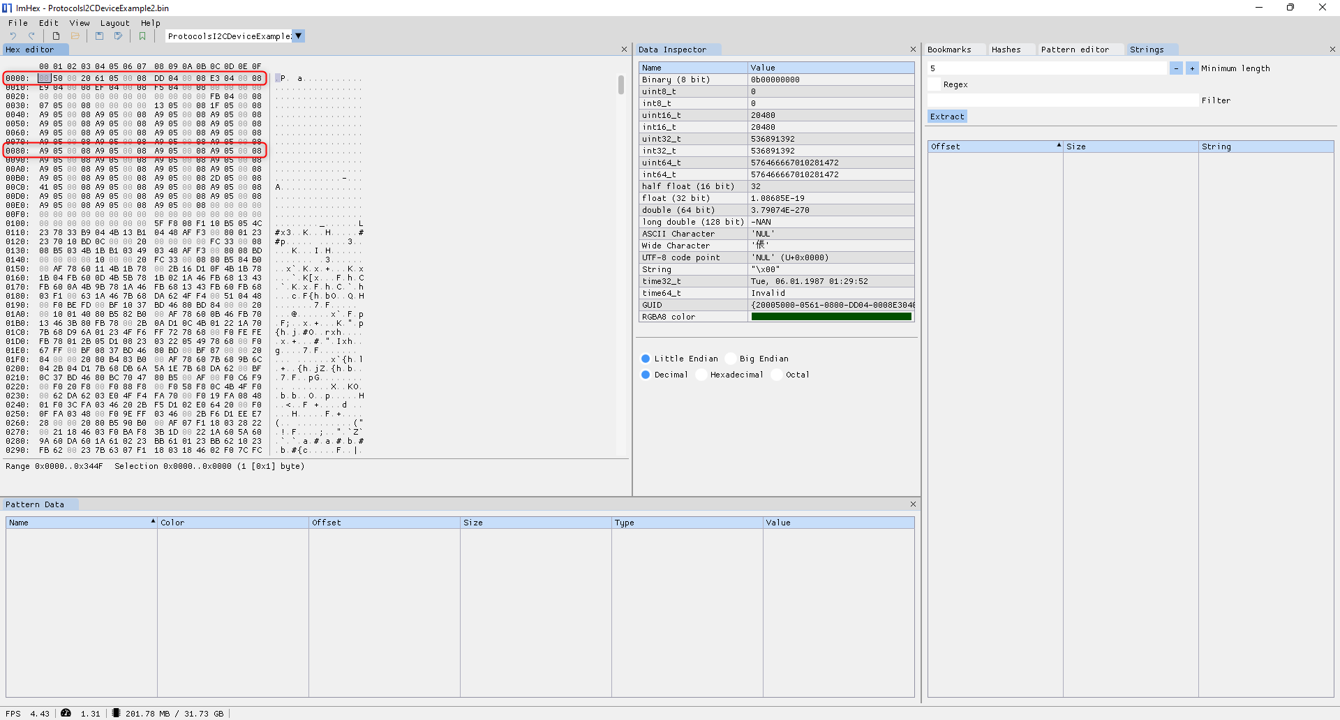
Figure 8.18: Hexdump of the firmware
8.2.5.4 Analyze using the Logic Analyzer
Now let’s analyze the I2C communication we did with the Bus Pirate using a cheap Logic Analyzer and Pulseview. Connect everything to a breadboard and set up the Logic Analyzer to dump the SCL and SDA lines. Here is the chaotic version of how it should look like:
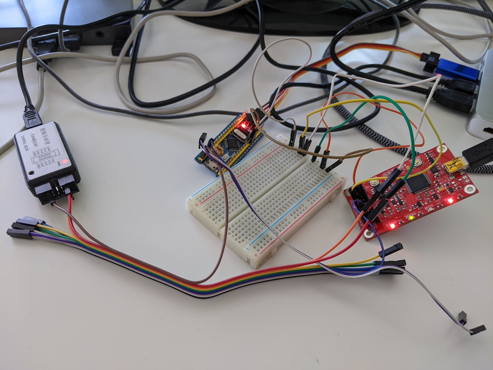
Figure 8.19: Chaotic Lab Setup
You can download the Pulseview dump here
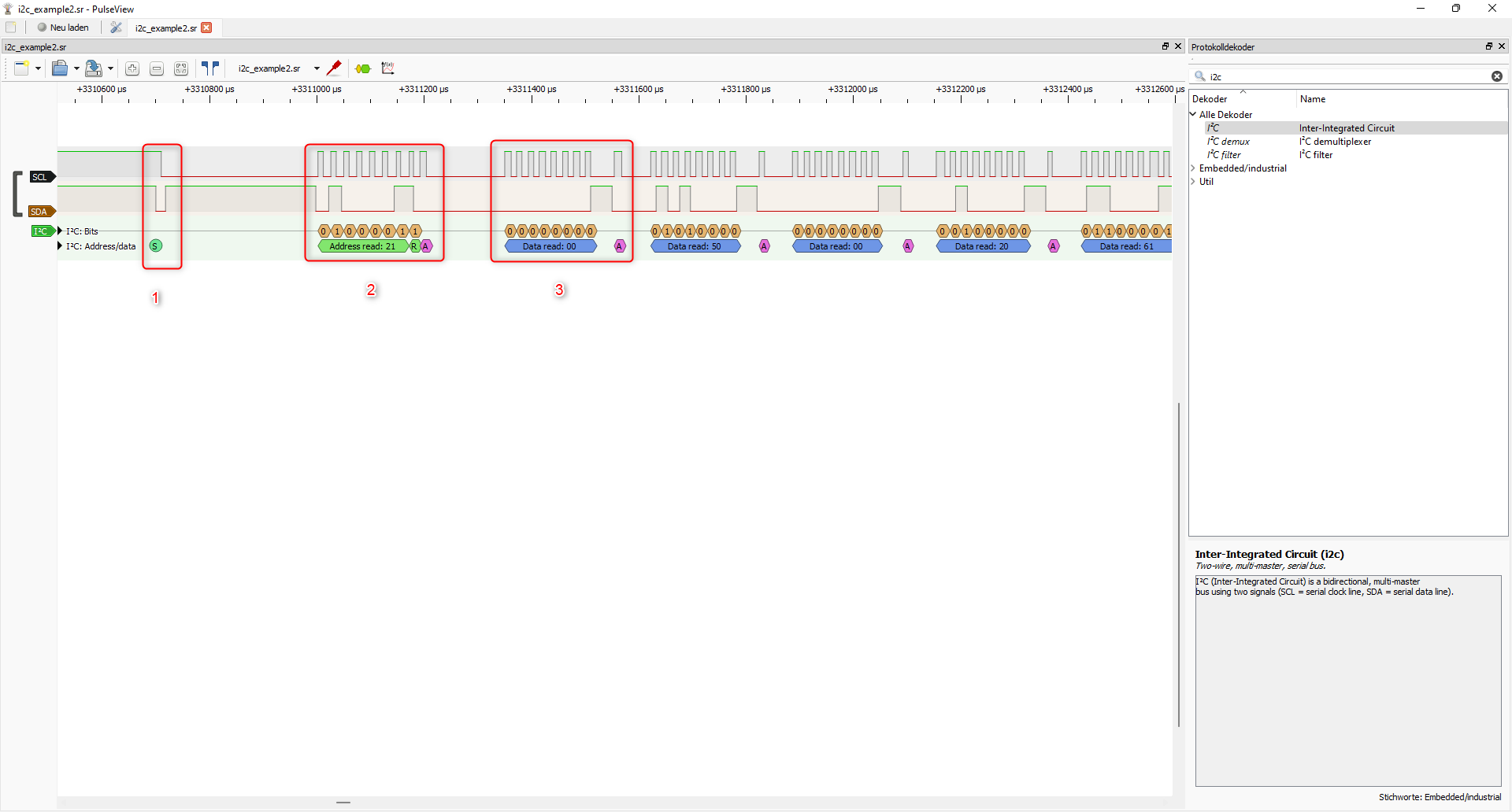
Figure 8.20: START and READ condition
At 1 you can see the START condition, SDA transitions from HIGH to LOW while SCL is HIGH. At 2 we see the address. Pulseview separates the address and the Direction bit, taken together (0b01000011) we have the 0x43 we used in the Bus Pirate. 3 is the transmission of the first byte from the Bluepill to the Bus Pirate, followed by an ACK send by the Bus Pirate.
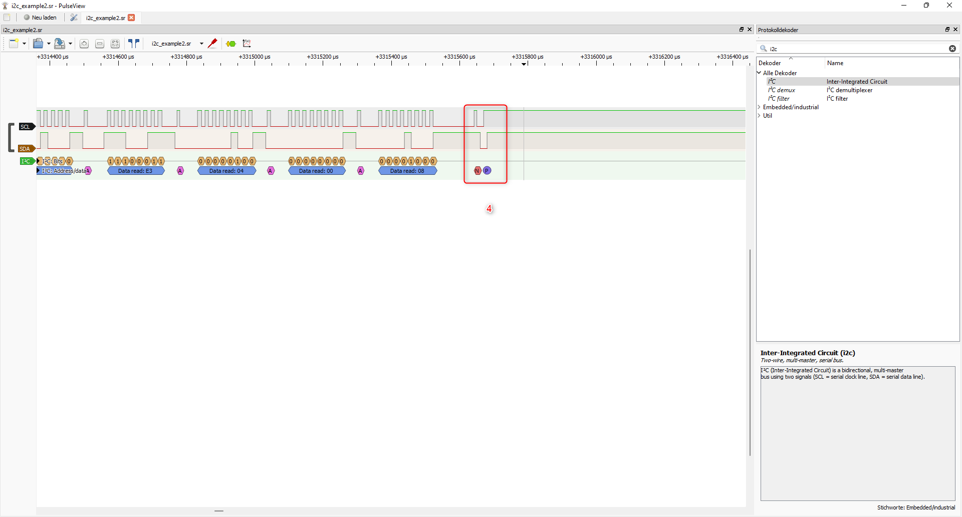
Figure 8.21: NACK and STOP condition
After successfully receiving and ACKnowleding 15 bytes, the last byte is NACKed by the Bus Pirate directly followed by a STOP condition: A transition from LOW to HIGH while SCL Is HIGH. (4)
The next transaction issued by the Bus Pirate is the WRITE of the relative flash address we have done before:
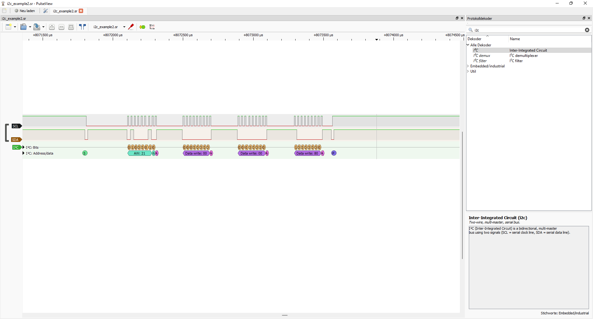
Figure 8.22: WRITE 0x000080
We see, the Direction bit changed to 0 and the Bluepill actually receives and acknowledges three bytes. Then the controller stops the transaction using a STOP condition.
8.2.5.5 FTDI: Automating the firmware extraction
Next we will extract the whole firmware in an automated way using the Tigard. The Tigard has two interfaces, from which the first one can be used for UART (Port A or “UART Header”). Connect this to the Bluepill USART1 Port. The other one (Port B or “JTAG Header”) will be connected to the I2C1 port of the Bluepill.
For more information on the Monodon firmware and its interfaces and port, see section 8.3.
Connections of the UART Header of the Tigard:
- Voltage switch to
VTGT RX(Tigard) ->A9(Bluepill)TX(Tigard) ->A10VTGTto a 3.3V of the BluepillGNDto aGNDof the Bluepill
The second port of the Tigard is a multi-purpose port. Set the protocol switch of the Tigard to SWD/I2C.
Connections of the JTAG header:
TDI/COPI/SDA->B7TCK/CLK/SCL->B6
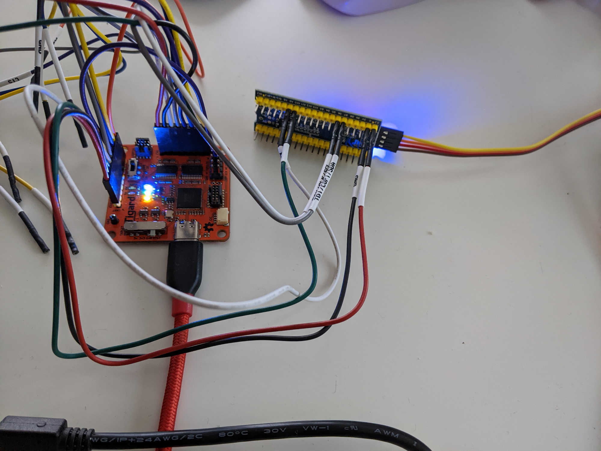
Figure 8.23: Tigard connected to the Bluepill
For more information on the Tigard and everything related check out section 9.3.
The script for automated extraction is pretty easy:
from pyftdi.i2c import I2cController

i2c = I2cController()
i2c.configure('ftdi://ftdi:2232:TG110505/2')

with open('firmware.bin', 'wb') as f:
    for i in range(0, (128*1000) // 16):
        slave = i2c.get_port(0x21)
        data = slave.read(readlen=16, start=True)
        f.write(data)
        print("Downloaded 16 byte")
You can download the source code here from GitHub.
While the extraction runs, connect to the UART port via your favorite terminal. There you should see the log:
Hello world!
I2C1: READ FLASH ended! 16 bytes transferred
I2C1: READ FLASH ended! 16 bytes transferred
I2C1: READ FLASH ended! 16 bytes transferred
I2C1: READ FLASH ended! 16 bytes transferred
I2C1: READ FLASH ended! 16 bytes transferred
[...]
8.3 Monodon Firmware
The Monodon firmware implements multiple protocols and interfaces used in previous chapters to demonstrate the usage of different tools and describe embedded protocols. Monodon is currently used in multiple examples through the book (see below).
You can find the compiled firmware as a bin file here on GitHub. You can flash the firmware using the STM32CubeProgrammer.
Monodon is implemented for the Bluepill. You can find the source code as a STM32CubeIDE project on GitHub: embeddedsecurity-io/monodon.
Please also check my overview on the Bluepill board for the Pinout and more information.
The Monodon firmware has SWD enabled. Once you flashed the Monodon firmware once, can re-flash your Bluepill without setting the BOOT0 pin to 1.
8.3.1 USART1
USART1 is configured as TX only UART interface with 9600 baud, 8 bit word length, 1 stop bit, no parity bit. It is used by the protocols implemented on the other interfaces (USART2 and I2C1) to output log and debug messages. Additionally a Timer (TIM2) based interrupt is used to transmit the string “Hello world!” every 5 seconds. The UART transmission is done via Interrupt mode. See the following examples, which use this interface:
- Decode a UART signal using a cheap Logic Analyzer and PulseView: Section 8.1.2
Pins:
TX:PA9RX:PA10
The output of logs has a low priority. This means the preemption priorities for the interrupts TIM2 and USART1 are lower than those of USART2 and I2C1.
8.3.2 USART2
USART2 is configured as RX/TX UART interface with 9600 baud, 8 bit word length, 1 stop bit, no parity bit. USART2 implements a simple protocol to interact with, which can be used to extract the firmware via UART. The details of this protocol are described in section 8.1.4.
UART RX is implemented in Interrupt mode. The received command is parsed and answered in blocking mode within RX interrupt handler code.
Check out the following examples, which use the protocol implemented via this UART interface:
- Extract the firmware of a device via a UART using the Bus Pirate and a FTDI Chip (Tigard): Section 8.1.4
Pins:
TX:PA2RX:PA3
8.3.3 I2C1
I2C1 is configured at 100kHz with the target address 0x21 with 7 bit addresses. It currently implements target-receiver and target-transmitter functionality. This functionality allows to extract the extract bytes from the internal flash via I2C. The protocol is described in section 8.2.5. The callback HAL_I2C_AddrCallback() is used to determine the direction of communication and enable the respective interrupts for RX or TX.
Please check the following examples, which use this interface for more information on the protocols implemented via I2C:
- Find the address of a target on a I2C bus using the Bus Pirate: Section 8.2.3
- Extract the firmware of a device via I2C using the Bus Pirate: Section 8.2.5
Pins:
SDA:PB7SCL:PB6